Next Dreve Mouthguard Workshops: 21.04.2023, 22.09.2023
At a cursory glance, one could overlook the innovation, it is so inconspicuous. But the impression is deceptive: The latest achievement from Dreve Dentamid GmbH is securely enclosed between two EVA foils.
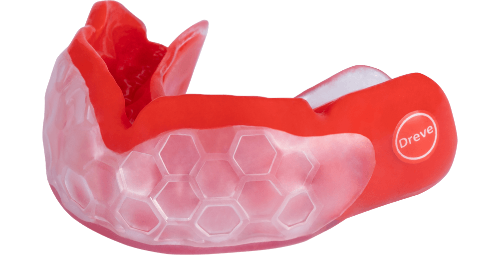
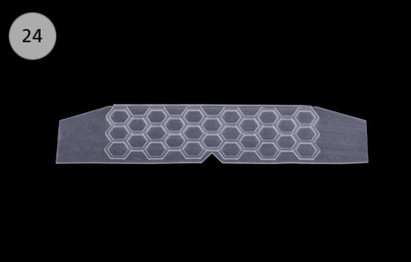
The pioneering insert with a distinctive honeycomb structure consists of a digitally printed silicone material with highly flexible properties. Due to its hexagonal shape, it perfectly absorbs pressure and tensile forces and dissipates them safely.
With the digital printing process it is now possible to build structures that can better absorb the forces and distribute them to the face mask. This means that the tooth structures are better protected than with the analogue predecessor model with a rigid protective insert. The filigree inlay with a final hardness of approx. 43 Shore A absorbs the force acting on the teeth, gums and bone structure thanks to its bionic honeycomb structure, splits them very effectively at the connection points and distributes them over the entire protected area. The forces acting directly on the jaw are thereby considerably minimized and the risk of fractures is effectively reduced.
In close cooperation with sports scientists and professional athletes, the material specialists from Unna have succeeded in combining two different methods - traditional thermoforming technique and digital printing technology - into one product that exceeds the protection and comfort of mouthguards on the market today.
The Dreve Mouthguard professional 3D corresponds to a central working premise in the development of new products because it combines the best of two worlds.
Not only athletes benefit from the innovative Dreve Mouthguard professional 3D. Compared to the purely analog mouthguard production, the laboratory saves the otherwise necessary medium thermoforming process and finishing steps. The printed insert is delivered ready-made and only needs to be individually cut and applied to the film.
Depending on the level of experience, 5 to 10 minutes of working time can be saved. With a field hockey team for the Olympic Games, for example, this saves up to 3 hours!

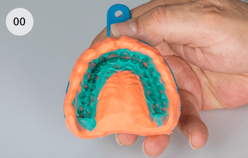
The dentist takes an impression of the upper and lower jaw. The upper jaw impression should reproduce the teeth, the gums up to the fold, all muscles and ligaments as well as the hard palate as precisely as possible (00).
Ideally, the sandwich technique should be chosen for this (e. g. with Zerosil® soft and Dynax® light).
The lower jaw impression only serves as an opposing bite and can be taken with an alginate or with Zerosil® soft.
The models should preferably be made from plaster of class III or higher, which has been mixed under vacuum.
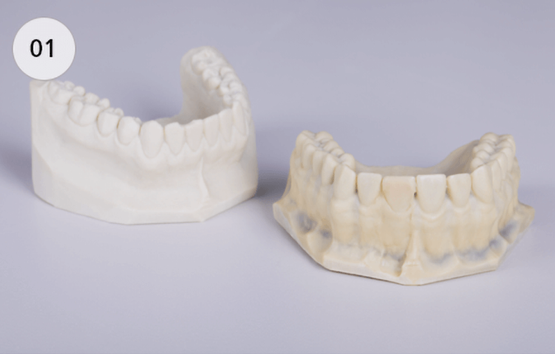
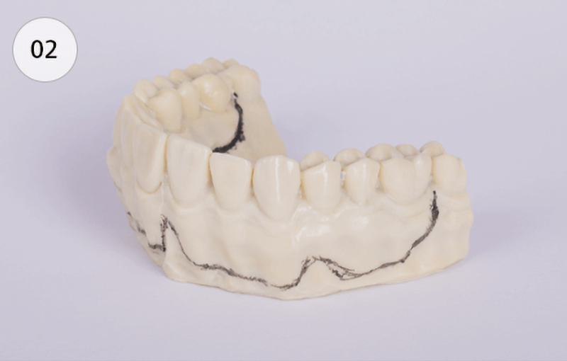
A homogeneous and bubble-free plaster surface is important for the problem-free wearing comfort of the mouthguard, i. e. positive bubbles are carefully erased, negative bubbles are blocked out (01).
If there are undercut bridge parts or narrow gaps in the upper jaw, these must also be blocked out.
Preparation of the upper jaw model
Marking the outer edge of the mouthguard:
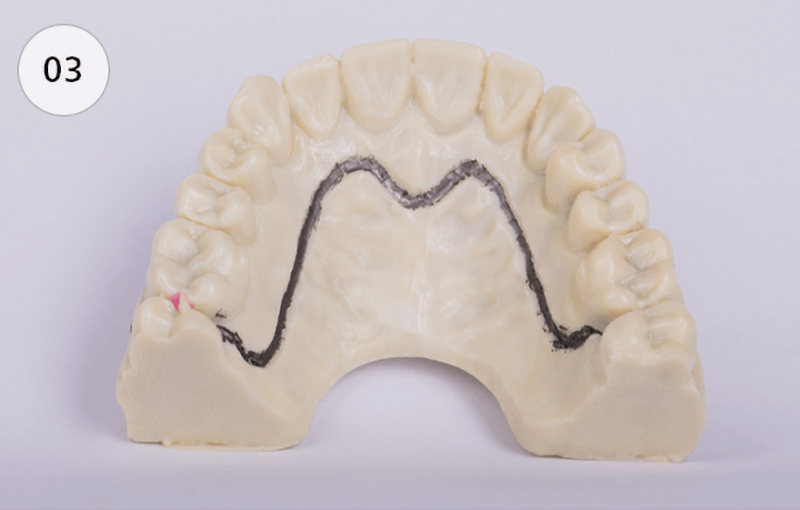
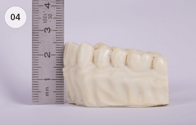
To ensure the desired layer thicknesses of the finished mouthguard, the model is ground back on the plaster trimmer to a maximum height of 25 mm in the region of the front teeth and to 22 mm in the region of the lateral teeth.
The opening of the palatal roof is recommendable in order to achieve a better adaptation result of the thermoforming foil.
All distal parts of the model lying outside the marking must also be trimmed (04).
In order to counteract any risk of the model breaking during the thermoforming process, the model base must be designed to be level and must not be wiggly.
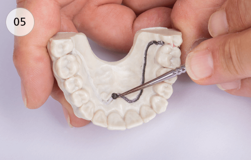
The palatal border is rubbed into the plaster model with a modeling tool about 1 mm deep and 1 mm wide (05). The step resulting from this is slightly broken towards the gum line.
Reason: The palatal edge of the mouthguard can be thinned down to the palate level, i. e. a step between the palate and the mouth guard, which irritates the tongue, is minimized.
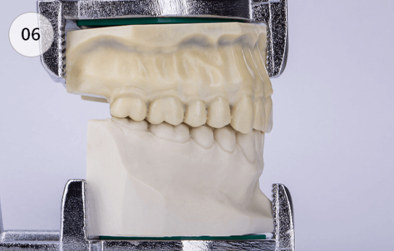
The upper jaw model, which has been prepared to this point, is removably fixed in an articulator, together with the lower jaw model (06).
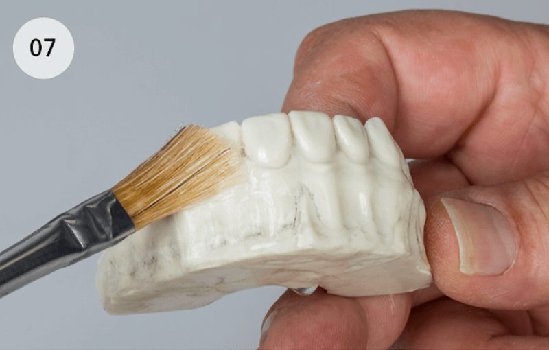
Soak the upper jaw model well with water and isolate with an alginate solution (e. g. Isolat film) (07).
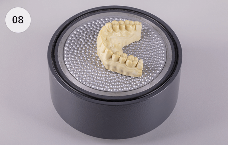
The model is positioned on the knobbed plate of the granules pot. When doing so, take care that the highest point of the model (anterior teeth region) is as close as possible to the center of the knobbed plate and thus to the heat center (08).
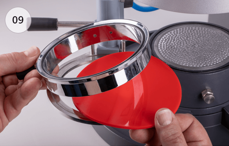
Place Drufosoft® 3 mm into the plate holder, put the tension ring on top and swivel the plate holder in (09).
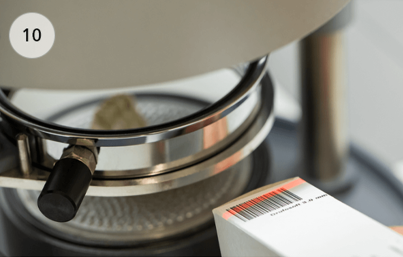
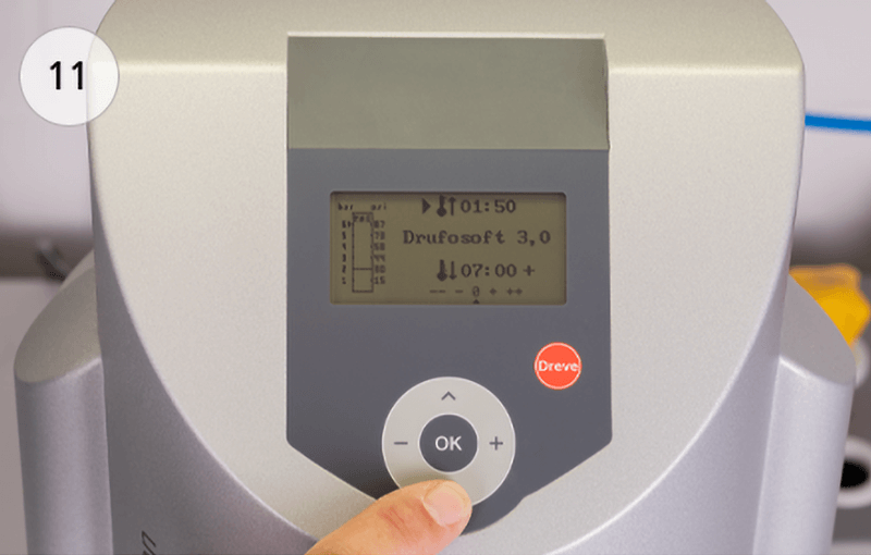
Then, also swivel the heater in and scan the respective barcode on the foil package (10).
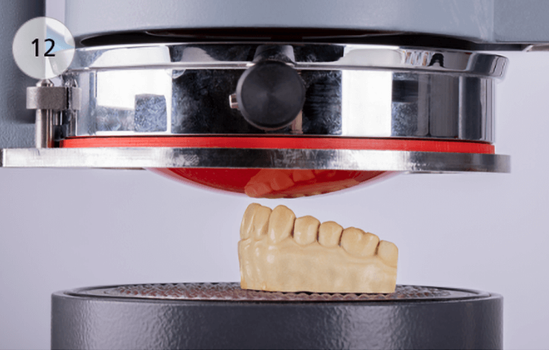
Alternatively, the heating time of 1:50 minutes can also be set manually (11). Start the heating process. After the heating time has expired, Drufosoft® 3 mm visibly sags downwards (12).
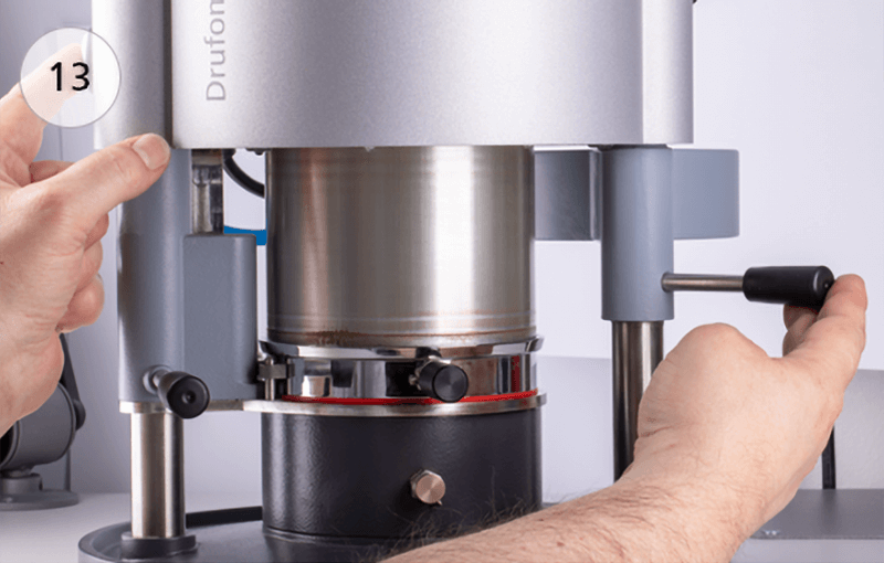
Start the thermoforming process (13) (also see instructions for use of the Drufomat scan).
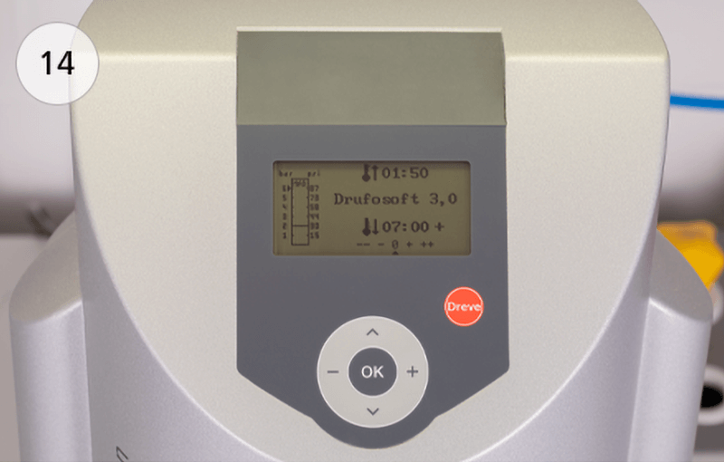
Let the foil cool down under pressure for at least 7:00 minutes (14).
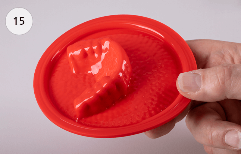
Open the Drufomat scan and remove the foil including the model (15).
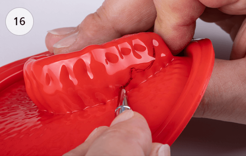
For better control, the margins of the mouthguard should be transferred to the Drufosoft® foil.
The following rules apply here:
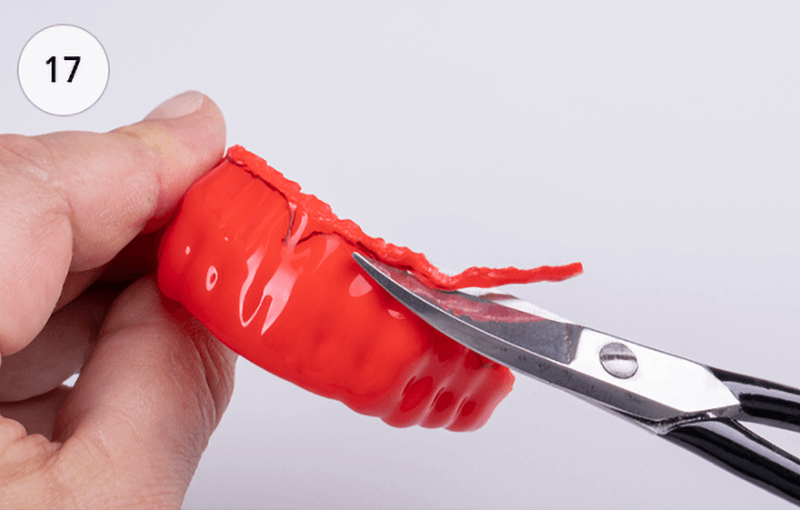
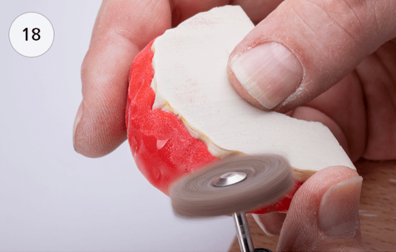
The final shape of the mouthguard is cut out of the foil along the markings with scissors (17). Round off and smoothen surfaces and interfaces e. g with UltraTrimm medium (18).
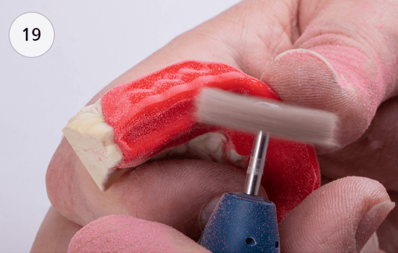
For the counter bite, a bite plateau should be ground into the mouthguard occlusally (19).
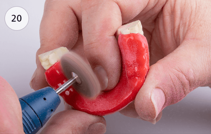
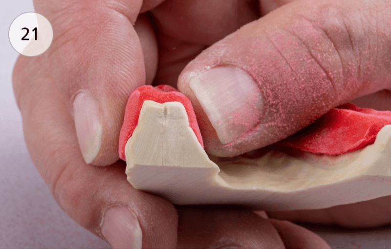
The entire palatal area must be thinned and smoothened to a maximum of 1.5 mm (20 & 21).
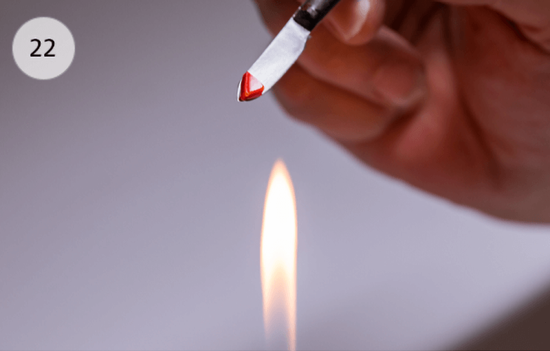
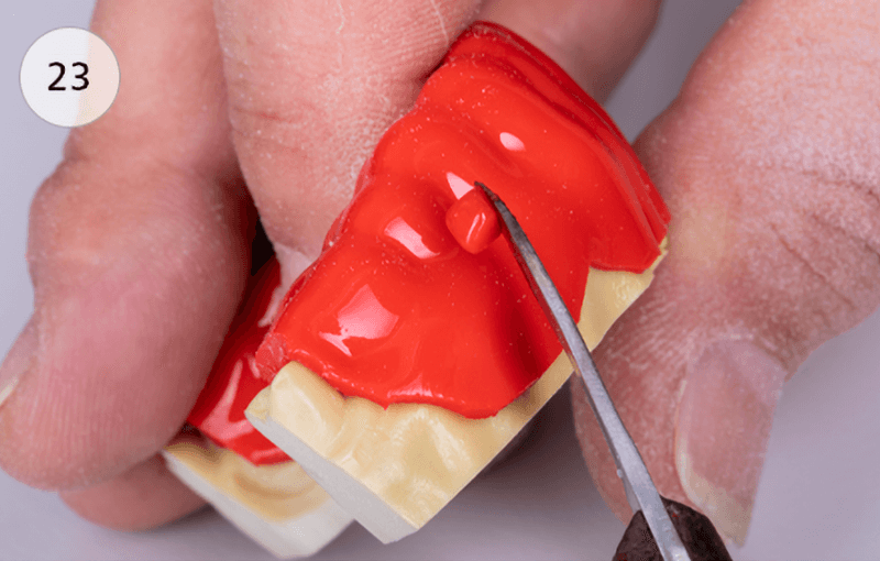
Deep incisions, e.g. in the area of interdental spaces, should be filled with small amounts of Drufosoft® in order to avoid potential air inclusions during the lamination process. By heating over the Bunsen burner, the required amount of Drufosoft® is softened (22) and applied into the interdental spaces with slight pressure (23). Then smoothen the edges with UltraTrimm light.
The new insert consists of a digitally printed silicone material with highly flexible properties and a final hardness of approx. 43 Shore A. The force acting on the teeth is optimally absorbed by the bionic honeycomb structure of the insert, split up very effectively via the connection points, and distributed over the entire protection area.
The forces acting directly on the teeth are thereby considerably minimized and the risk of fractures is effectively reduced. In order to ensure a good adaptation to the sport and the age of the athlete, the inserts are offered in 2 protection versions (basic and premium) and in 2 sizes (L and XL).
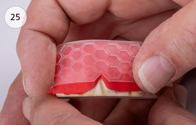
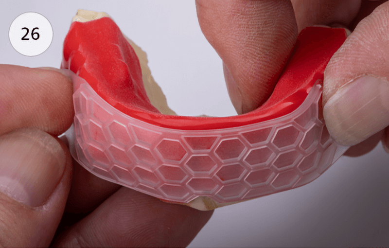
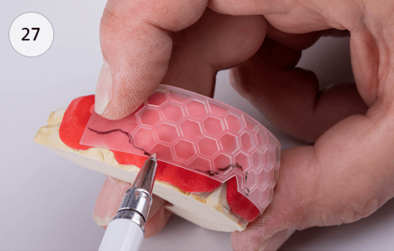
Thermoform the first foil (Drufosoft® 3 mm, coloured) and work it out (see chapters 3 and 4). Then bring the Professional 3D insert in position on the first foil, with the honeycomb structure facing up. Make sure that the lower incision of the insert corresponds with the position of the lip frenulum and that the crossbar of the opposite edge is flush with the cutting edges of the anterior teeth (25). Fix the insert in this position with one finger and place it very close to the first foil on one side in a distal direction (26). To ensure optimal lamination between the first and the second thermoforming foil, the dorsal end of the insert must be designed to be by 3 mm shorter than the margin of the mouthguard.
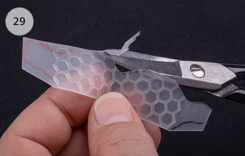
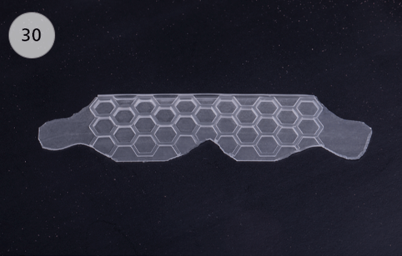
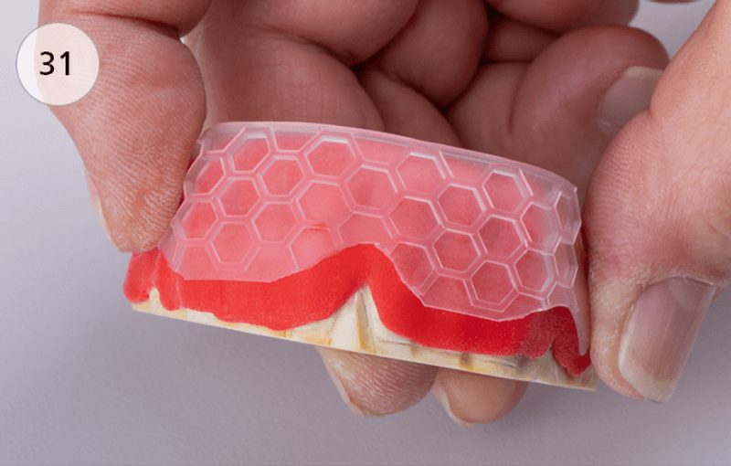
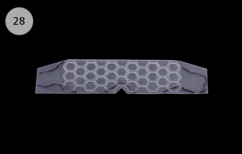
In this fixed position, the dorsal end of the insert can now be shortened according to the specifications of the first foil. To do this, draw the individual shortening on the insert with a pen, then carry out the same process on the other side of the mouthguard (26 & 28). Finally, cut the appropriate expansion of the 3D insert along the drawing using scissors (29 & 30). To be on the safe side, check the position and expansion of the 3D inlay on the first film again and improve if necessary (31).
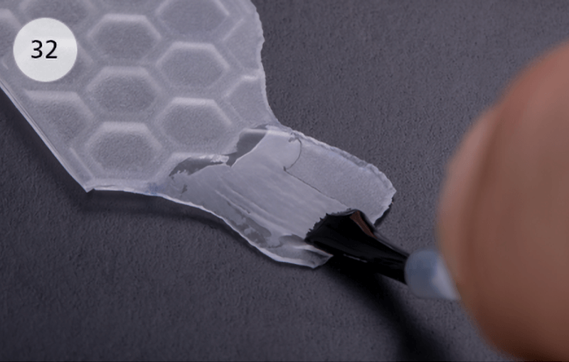
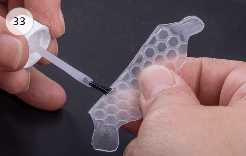
Place the finished, customized 3D insert with the honeycomb structure facing down on a flat surface and thinly wet the two end flanks as well as the area of the upper crossbar with Protector adhesive (32 & 33). The adhesive needs about 2 minutes to develop the optimal adhesive strength.
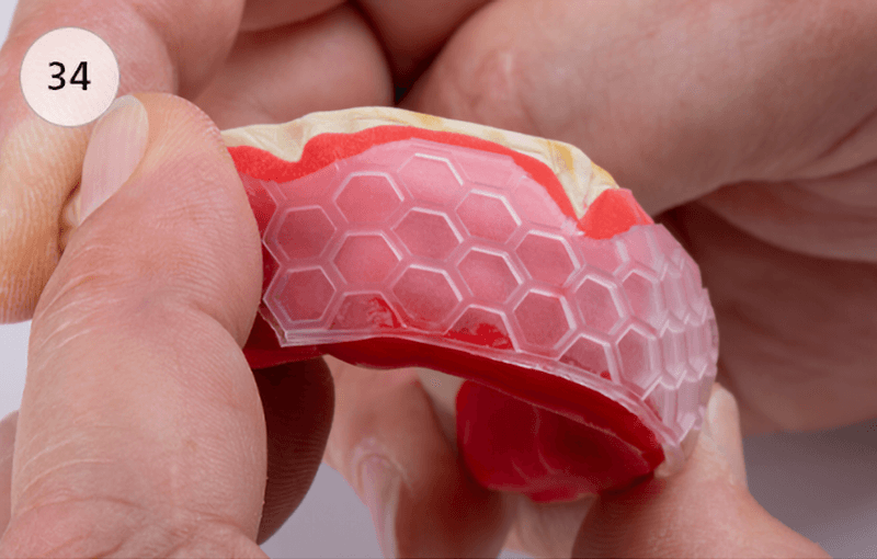
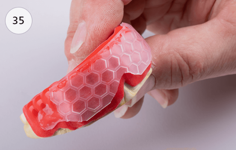
Then the 3D insert can be attached to the first thermoforming foil with firm pressure (34). Make sure that the insert is in the correct position (see chapter 6). If the fit is inaccurate, the insert can be loosened again to correct it (35).
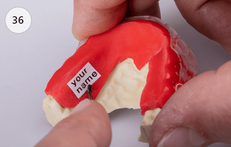
The design of a Dreve mouthguard is internationally established, except for the design in the visible front teeth area:
on the first foil (36–38).
The X-ray opaque stripe enables the mouthguard to be recognized on X-ray images (e.g. in case of unconscious patients) and is fixed on the first foil by a punctual melting. The entire front teeth area can be designed individually (e.g. with club logos, flags, banners etc.).
Important: To ensure that the second foil is completely and securely laminated, all stickers must have a minimum distance of 2 mm from the edge of the mouthguard.

In order to ensure that the inserted stickers can be recognized, the lamination foil is always a transparent one.
A Drufosoft® 3 mm foil is required for lamination.
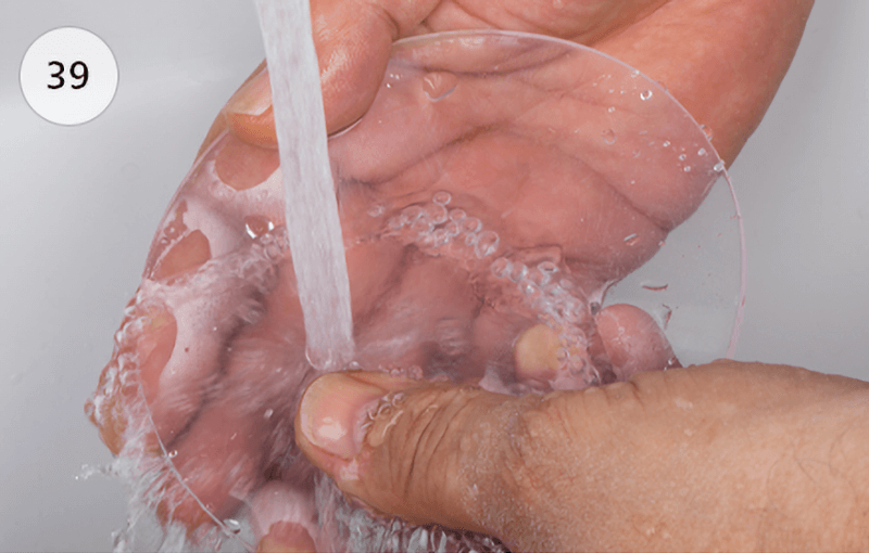
Important: Due to the production process, there may be a very thin film of lubricant on the Drufosoft® foil. Therefore, always clean the foil under running water and then dry it with a cloth (39).
Positioning of the model including the first foil as well as the preparation of the Drufomat scan takes place as already described under point 3 (Thermoforming foil 1).
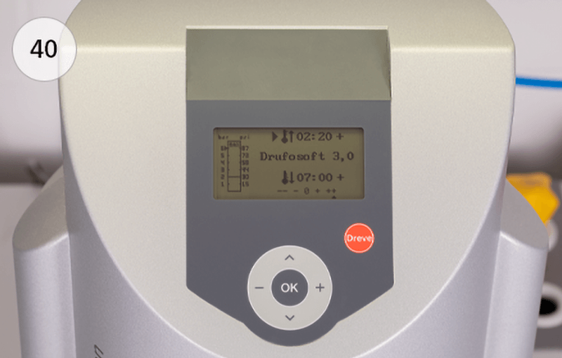
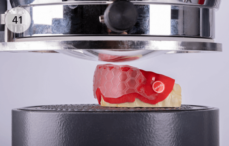
The heating time for the Drufosoft® foil to be laminated is 2:20 minutes (40). Contact between the first foil and the second foil during heating is not a problem (41).
Start the thermoforming process and let the foil cool down under pressure for at least 07:00 minutes. After half of the specified cooling time has elapsed (3:30 remaining time in the display), the ring valve on the Drufomat scan can be opened slightly for faster cooling. Open the Drufomat scan and remove the mouthguard for final processing.
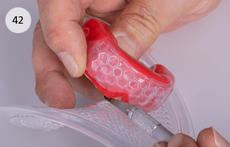
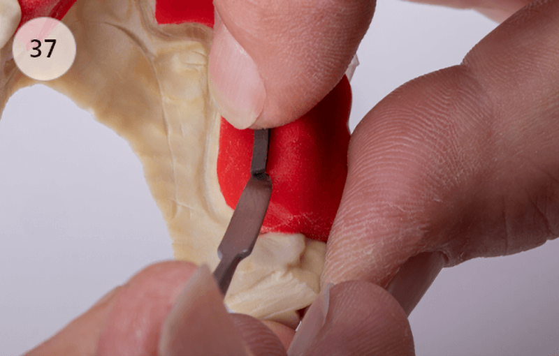
With a hot scalpel (42) or a pair of scissors, the mouthguard is cut out along the first foil, and then the edge is brought into its final shape and is homogenized with e.g. UltraTrimm medium.
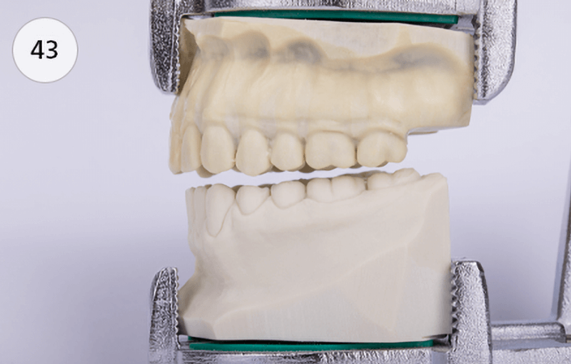
Place the upper jaw model back in the articulator and block the occlusion by 2,5–3 mm (measured in the molar area) (43). Put the mouthguard back on.
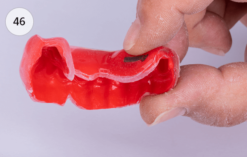
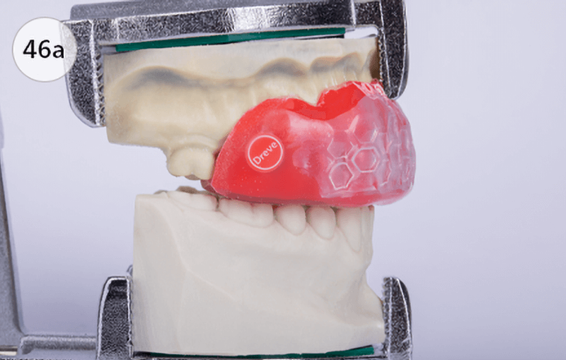
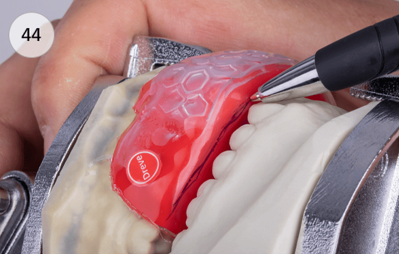
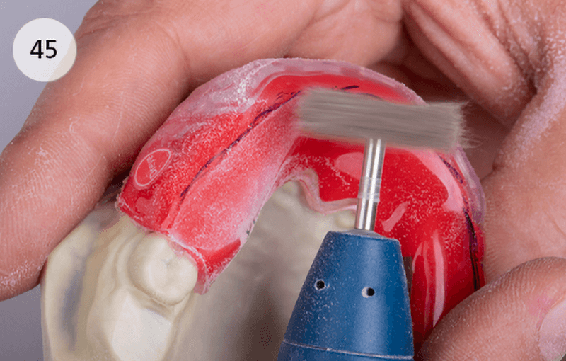
Check the mouthguard’s bite blockage and transfer the vestibular limitation of the lower jaw teeth on the mouthguard with a pen (44). On the palatal side of this marking, a plateau for the lower jaw teeth is created with UltraTrimm until the previously set bite-lock is almost reached (45). The resulting occlusal-vestibular material wall additionally protects the incisal edges and cusp tips of the lower jaw teeth when a bite occurs (46 & 46a).
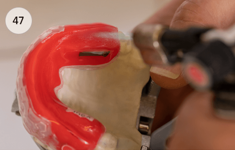
Heat the plateau evenly with a pointed flame under flowing movements (47).
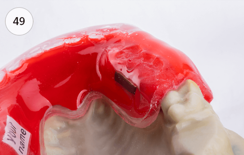
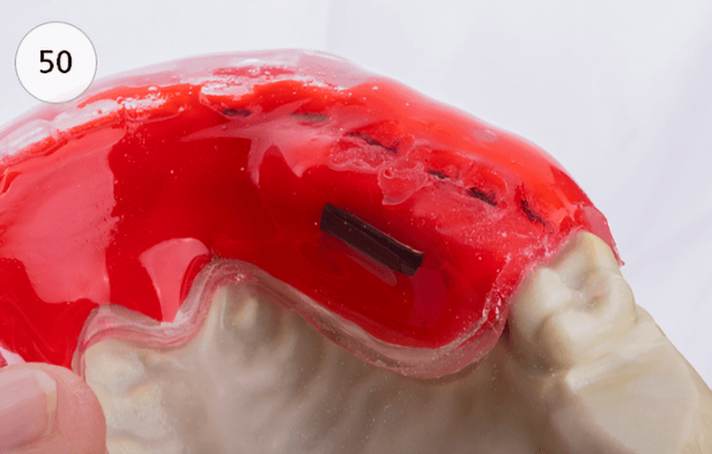
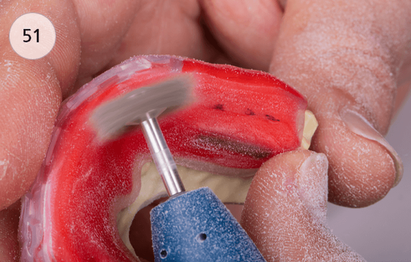
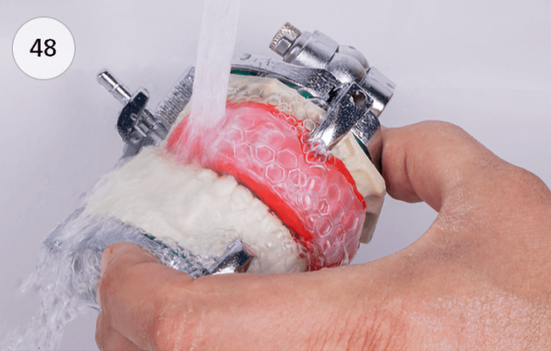
Close the articulator with slight pressure. To prevent deformation of the mouthguard, it should then be cooled immediately under running cold water (48). The impressions of the lower jaw teeth are ground back down to the cusp tips of the lateral teeth (49–51).
Reason:
An unphysiological fixation of the lower jaw leads to a loss of concentration in the athlete and rigid fixation of the lower jaw can prevent the possibility of a shock-absorbing sideways movement.
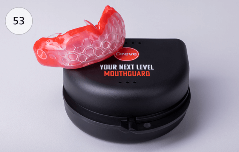
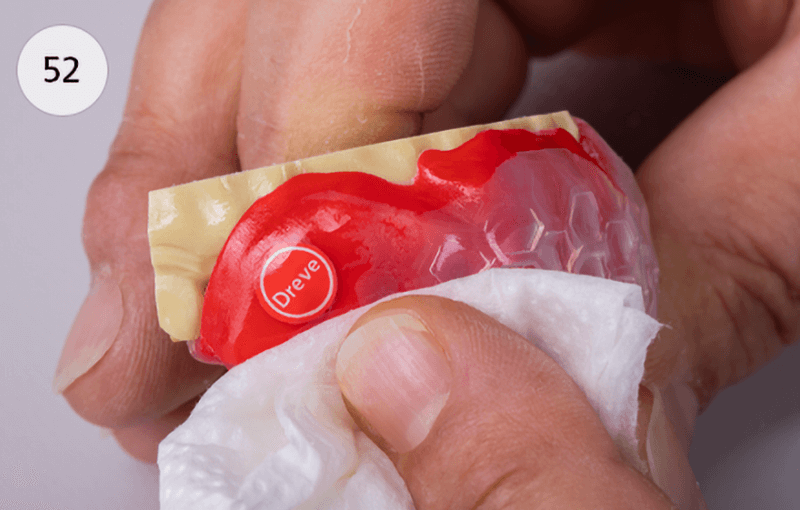
The Finishing Liquid is rubbed onto the mouthguard areas, which are roughened by the milling, with a soft cloth, applying gentle pressure in circular movements (52). As a result, the surface is slightly loosened and then hardens again to a highly glossy surface (53).